To begin exporting your PCB files, open the Tools menu and select CAM Wizard.

When the next window appears, click Next to continue.

On the following screen, choose Generate Gerber files.

You’ll then be prompted to assign names to your Gerber files.

Click Next to proceed.
On the next screen, choose Inches as the unit of measurement (this is the default setting). Based on your design specifications, select the appropriate format, since Bittele accommodates the highest resolution, you can opt for 2.5. Then, click Next to continue.

In the next menu, be sure to select all available options under the “Plot” section. At the same time, leave every checkbox under the “Mirror” section unchecked to prevent any of your board layers from being produced in reverse. Then click Next.

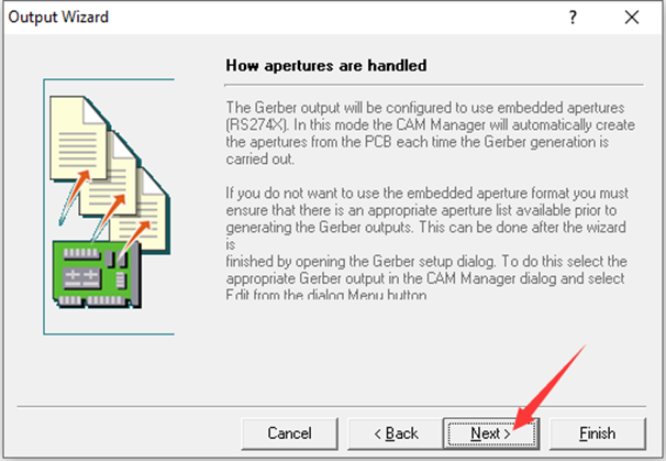
Move to the next screen and leave the default boxes selected, then click Next again.

On the following menu, choose Characters while leaving the other settings at their default values.

For the final three menus in the wizard, simply click Next twice and then click Finish to complete the Gerber file generation process.


At this stage, your Gerber files have been successfully created, but the drill files still need to be produced.
To do this, right-click in the workspace area and select “Insert NC Drill...”

In the dialog box that appears, set the units to “Inches” (the default setting) and adjust the format to 2.5. Make sure the Optimize change location commands option is checked, and also check “Suppress trailing zeroes”. And then click OK.

Now that both your Gerber and drill files have been generated, right-click and select “Generate CAM files”.

A new folder named “CAM for (your file name)” will be automatically created in your directory.
Once this is done, right-click on that folder and select “Export”. Choose the destination where you’d like to save your files.

When the process is complete, you’ll find all your Gerber and drill files neatly stored inside the export folder you selected.


